§2.4 Diagrammatic Analysis of Perturbation Theory (Fermions)
We have got the expression of the exact Green’s function in the interaction picture:
\[\begin{equation} iG_{\alpha\beta}(x,x') = \frac{\ev{\hat{\mathsf{T}}\qty[\hat{\psi}_{I\alpha}(x)\hat{\psi}_{I\beta}^\dagger(x')\hat{S}]}{\Phi^0}}{\ev{\hat{S}}{\Phi^0}}, \label{green-function} \end{equation}\]where $\hat{H}_0 \ket{\Phi^0} = E_g^0 \ket{\Phi^0}$ and
\[\begin{equation} \begin{split} \hat{S} &= \hat{\mathsf{T}}\exp\qty[-\frac{i}{\hbar}\int_{-\infty}^{\infty} \dd{t} \hat{V}_{I}(t)]\\[.2cm] &= 1 - \frac{i}{\hbar} \int_{-\infty}^\infty \dd{t} \hat{V}_I(t) + \frac{1}{2!}\qty(\frac{-i}{\hbar})^2 \int_{-\infty}^{\infty} \dd{t}_1 \int_{-\infty}^{\infty} \dd{t}_2 \hat{\mathsf{T}}\qty[\hat{V}_I(t_1)\hat{V}_{I}(t_2)] + \cdots \end{split} \end{equation}\]For the interparticle potential $\hat{V}$ independent of particle spin, we have
\[\begin{equation} \int_{-\infty}^{\infty} \hat{V}_I(t')\dd{t}' = \frac{1}{2}\sum_{\alpha\beta}\int\dd[4]{x}\int\dd[4]{x'} \hat{\psi}_{I\alpha}^\dagger(x)\hat{\psi}_{I\beta}^\dagger(x')\hat{U}(x,x') \hat{\psi}_{I\beta}(x') \hat{\psi}_{I\alpha}(x). \end{equation}\]Wick’s theorem allows us to evaluate it as a perturbation expansion involving only wholly contracted field operators in the interaction picture. These contractions are just the free-field Green’s functions $G^0$, and $G$ is thereby expressed in a series containing $U$ and $G^0$. This expansion can be analyzed directly in coordinate space, or (for a uniform system) in momentum space and the procedure can be simplified as some diagrams which are known as the Feynman diagrams.
1. Feynman diagrams in coordinate space
1.1. Zeroth order
Consider the zeroth order of the numerator of $\eqref{green-function}$ where $\hat{S} = 1$, then
\[\begin{equation} \begin{split} \text{Zeroth order}& = \ev{\hat{\mathsf{T}}\qty[\hat{\psi}_{I\alpha}(x)\hat{\psi}_{I\beta}^\dagger(x')]}{\Phi^0} \\[.2cm] & = \ev{\hat{\mathsf{N}}\qty[\hat{\psi}_{I\alpha}(x)\hat{\psi}_{I\beta}^\dagger(x') + \hat{\psi}_{I\alpha}^{\bullet}(x)\hat{\psi}_{I\beta}^{\dagger\bullet}(x')]}{\Phi^0}\\[.2cm] & = iG_{\alpha\beta}^0(x,x') \end{split} \end{equation}\]This is the result we calculated in the previous post which represent the case of no interaction.
1.2. First order
Consider the first order of the numerator of $\eqref{green-function}$,
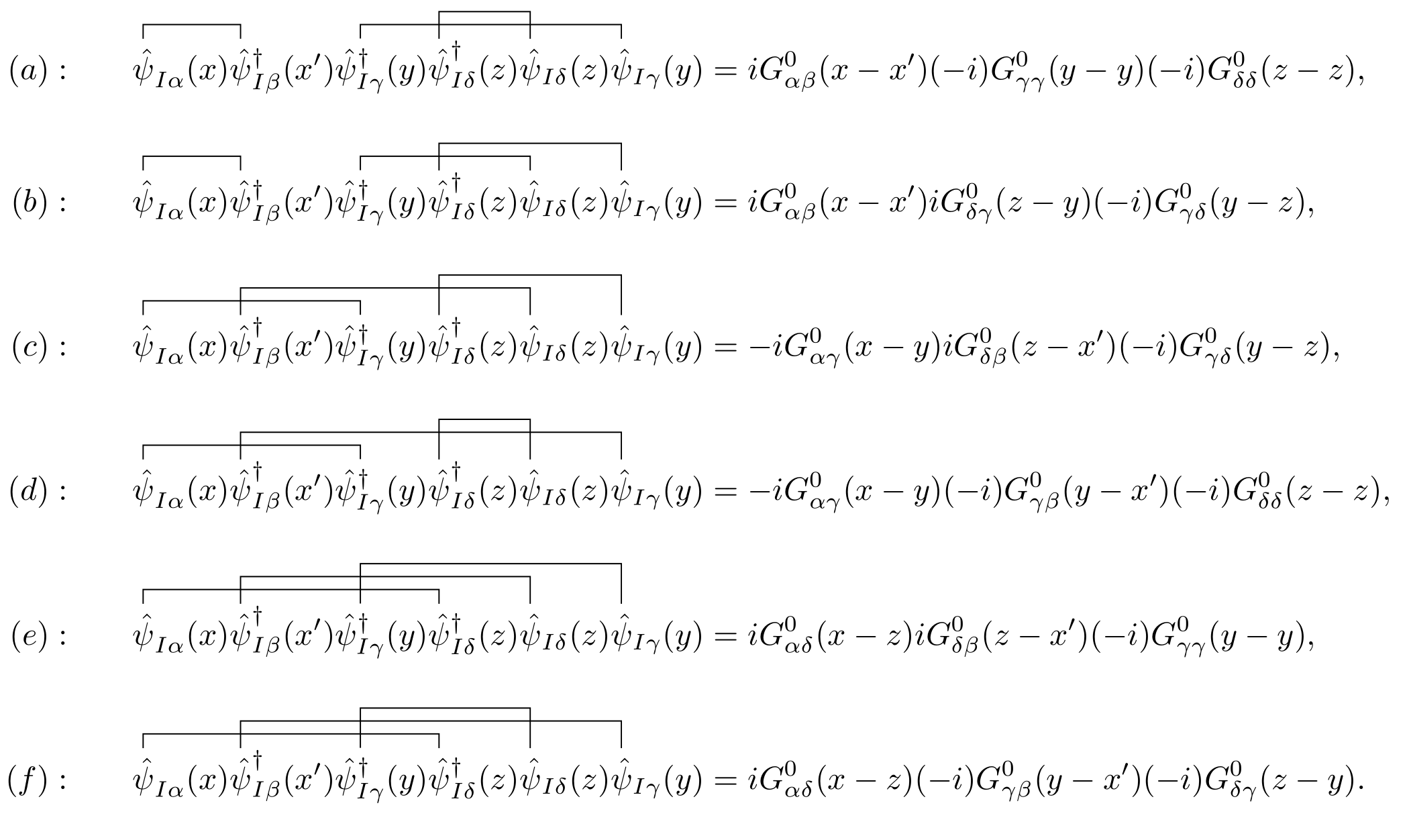
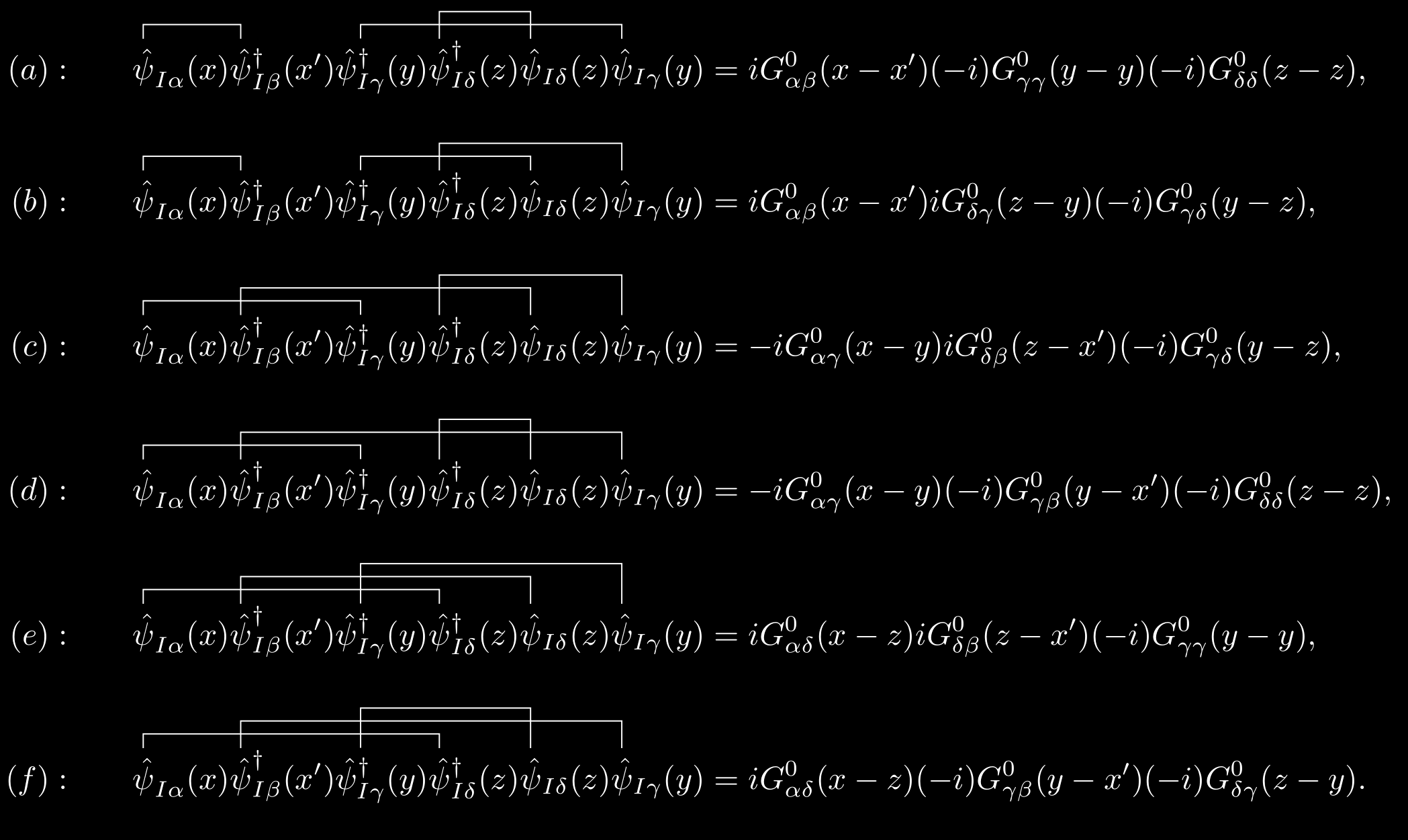
\[\begin{equation} \begin{split} \text{First order} & = -\frac{i}{2\hbar}\sum_{\gamma\delta}\iint\dd[4]{y}\dd[4]{z} \hat{U}(y,z) \textcolor{red}{\ev{\hat{\mathsf{T}}\qty[\hat{\psi}_{I\alpha}(x)\hat{\psi}_{I\beta}^\dagger(x')\hat{\psi}_{I\gamma}^\dagger(y)\hat{\psi}_{I\delta}^\dagger(z)\hat{\psi}_{I\delta}(z)\hat{\psi}_{I\gamma}]}{\Phi^0}}. \end{split} \end{equation}\]The red part of the above equation can be analyzed with Wick’s theorem where only the full contraction terms don’t vanish. Moreover, only the contractions of $\hat{\psi}$ and $\hat{\psi}^\dagger$ do not equal to zero. So actually, only six possible full contractions will contribute. To be explicit, I have used the traditional Wick contraction notation in the following figure.
1.3. Feynman diagrams in coordinate space
We now associate a diagram with each of the equations appearing in the above figure. The noninteracting Green’s function $G^0$ is denoted by a straight line with an arrow running from the second argument to the first, while the interaction potential is denoted by a dashed line.


TikZ code
1
2
3
4
5
6
7
8
9
10
11
12
13
14
15
16
17
18
19
20
21
22
23
24
25
26
27
28
29
30
31
\documentclass{article}
\usepackage[left=1em,right=1em]{geometry}
\usepackage{tikz}
\usepackage{amsmath}
\usepackage{physics}
\usepackage{tikz-feynhand}
\usepackage{tikz-feynman}
\usepackage{subfig}
\setlength{\feynhandlinesize}{1pt}
\tikzset{every picture/.style={line width=1pt}}

\begin{document}

\begin{figure}
    \centering
    \begin{tikzpicture}[scale=2,baseline=(a.base)]
        \begin{feynhand}
            \vertex (a) at (2,0); \vertex (b) at (0,0);
            \propag[fer] (a)node[below]{$x',\beta$}--  (b) node[midway,yshift=1.5em]{$G^0_{\alpha\beta}(x-x')$} node[below]{\vphantom{$x'$}$x,\alpha$};
        \end{feynhand}
    \end{tikzpicture}
\hspace{1cm}
\begin{tikzpicture}[scale=2,baseline=(a.base)]
    \begin{feynhand}
        \vertex (a) at (2,0); \vertex (b) at (0,0);
        \propag[chasca] (a)node[below]{$y$}--  (b) node[midway,yshift=1.5em]{$U(y-z)=V(\vb{y}-\vb{z})\delta(t_y-t_z)$} node[below]{$z$};
    \end{feynhand}
\end{tikzpicture}
\end{figure}

\end{document}
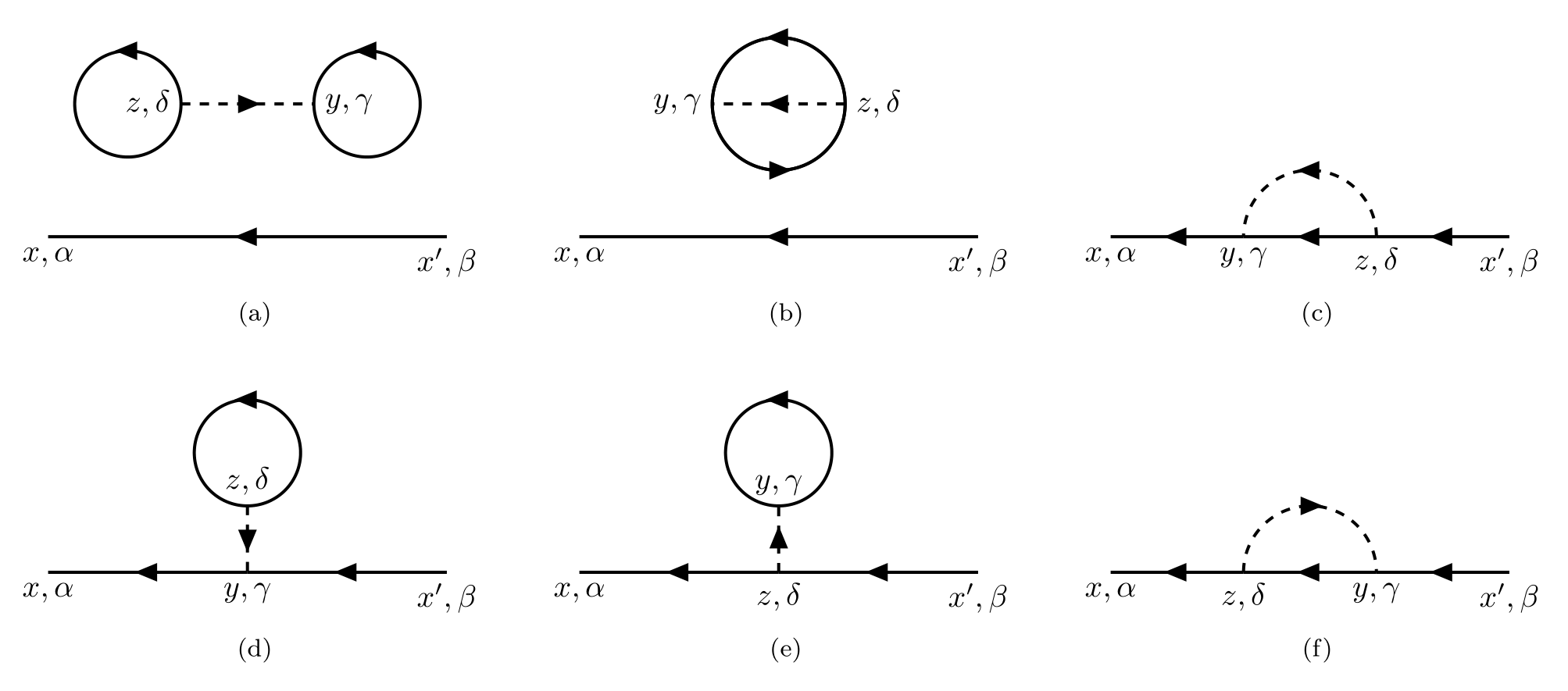
These six equations can be represented by the following six diagrams:
TikZ code
1
2
3
4
5
6
7
8
9
10
11
12
13
14
15
16
17
18
19
20
21
22
23
24
25
26
27
28
29
30
31
32
33
34
35
36
37
38
39
40
41
42
43
44
45
46
47
48
49
50
51
52
53
54
55
56
57
58
59
60
61
62
63
64
65
66
67
68
69
70
71
72
73
74
75
76
77
78
79
80
81
82
83
84
85
86
87
88
89
90
91
92
93
\documentclass{article}
\usepackage[left=5em,right=5em]{geometry}
\usepackage{tikz}
\usepackage{amsmath}
\usepackage{physics}
\usepackage{tikz-feynhand}
\usepackage{tikz-feynman}
\usepackage{subfig}
\setlength{\feynhandlinesize}{1pt}

\begin{document}


\begin{figure}
    \subfloat[]{% a
        \begin{tikzpicture}[scale=1.5]
            \begin{feynhand}
                \vertex (a) at (0,0); \vertex (b) at (3,0);
                \vertex (c) at (1,1); \vertex (d) at (2,1);
                \propag[fer] (b) node[below]{$x',\beta$} to (a)node[below]{$x,\alpha$};
                \propag[fer] (c) circle [xshift=-0.4cm,radius=0.4,rotate=-90];
                \propag[fer] (d) circle [xshift=0.4cm,radius=0.4,rotate=-90];
                \propag[chasca] (c) node [left]{$z,\delta$} to (d) node[right]{$y,\gamma$};
            \end{feynhand}
        \end{tikzpicture}
    }
    \hspace{.4cm}
    \subfloat[]{% b
        \begin{tikzpicture}[scale=1.5]
            \begin{feynhand}
                \vertex (a) at (0,0); \vertex (b) at (3,0);
                \vertex (c1) at (1,1); \vertex (c2) at (2,1);
                \propag[fer] (b) node[below]{$x',\beta$} to (a)node[below]{$x,\alpha$};
                \propag[fer] (c1) circle [xshift=0.5cm,radius=0.5,rotate=-90];
                \propag[fer] (c1) circle [xshift=0.5cm,radius=0.5,rotate=90];
                \propag[chasca] (c2) node [right]{$z,\delta$} to (c1) node[left]{$y,\gamma$};
            \end{feynhand}
        \end{tikzpicture}
    }
    \hspace{.4cm}
    \subfloat[]{% c
    \begin{tikzpicture}[scale=1.5]
        \begin{feynhand}
            \vertex (a) at (0,0); \vertex (b) at (1,0); \vertex (c) at (2,0);\vertex (d) at (3,0);
            \node at (a) [below]{$x,\alpha$};\node at (b) [below]{$y,\gamma$};\node at (c) [below]{$z,\delta$};\node at (d) [below]{$x',\beta$};
            \graph{ (d) -- [fer] (c)  -- [fer] (b)  -- [fer](a) };
            \propag[chasca] (c) arc(0:180:0.5);
        \end{feynhand}
    \end{tikzpicture}
}
\vspace{.3cm}

\subfloat[]{% d
\begin{tikzpicture}[scale=1.5]
    \begin{feynhand}
        \vertex (a) at (0,0); \vertex (b) at (1.5,0); \vertex (c) at (3,0);\vertex (d) at (1.5,0.5);
        \node at (a) [below]{$x,\alpha$}; \node at (c) [below]{$x',\beta$};
        \node at (b) [below]{$y,\gamma$};
        \node at (d) [above]{$z,\delta$};
        \graph{ (c) -- [fer] (b)  -- [fer] (a) };
        \propag[chasca] (d) to (b);
        \propag[fer] (1.5,0.9) circle [radius=0.4,rotate=-90] ;
    \end{feynhand}
\end{tikzpicture}
}
\hspace{.4cm}
\subfloat[]{% e
\begin{tikzpicture}[scale=1.5]
    \begin{feynhand}
        \vertex (a) at (0,0); \vertex (b) at (1.5,0); \vertex (c) at (3,0);\vertex (d) at (1.5,0.5);
        \node at (a) [below]{$x,\alpha$}; \node at (c) [below]{$x',\beta$};
        \node at (b) [below]{$z,\delta$};
        \node at (d) [above]{$y,\gamma$};
        \graph{ (c) -- [fer] (b)  -- [fer] (a) };
        \propag[chasca] (b) to (d);
        \propag[fer] (1.5,0.9) circle [radius=0.4,rotate=-90] ;
    \end{feynhand}
\end{tikzpicture}
}
\hspace{.4cm}
\subfloat[]{% f
\begin{tikzpicture}[scale=1.5]
    \begin{feynhand}
        \vertex (a) at (0,0); \vertex (b) at (1,0); \vertex (c) at (2,0);\vertex (d) at (3,0);
        \node at (a) [below]{$x,\alpha$};\node at (c) [below]{$y,\gamma$};\node at (b) [below]{$z,\delta$};\node at (d) [below]{$x',\beta$};
        \graph{ (d) -- [fer] (c)  -- [fer] (b)  -- [fer](a) };
        \propag[chasca] (b) arc(180:0:0.5);
    \end{feynhand}
\end{tikzpicture}
}
\end{figure}

\end{document}
- The terms $a$, $b$, $d$, and $e$ contain a Green’s function with both arguments at the same time, which is indicated by a solid line closed on itself, i.e. $i G_{\alpha\beta}(x,x)$. Their integral eventually leads to a constant, leaving only the free propagator $G^0$.
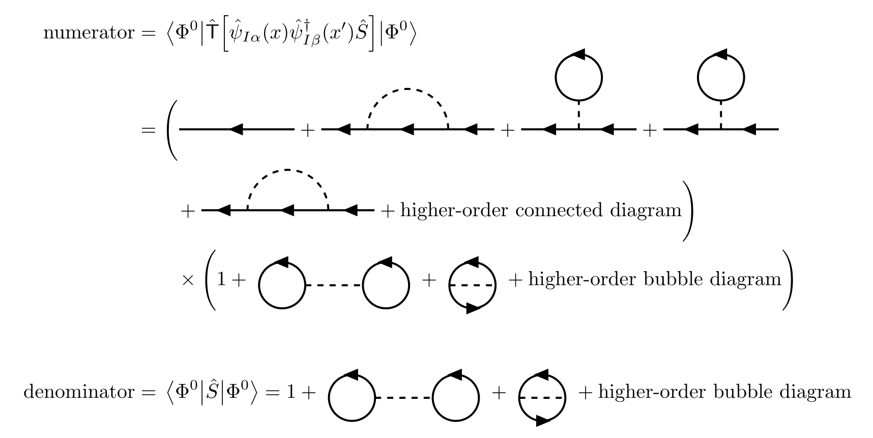
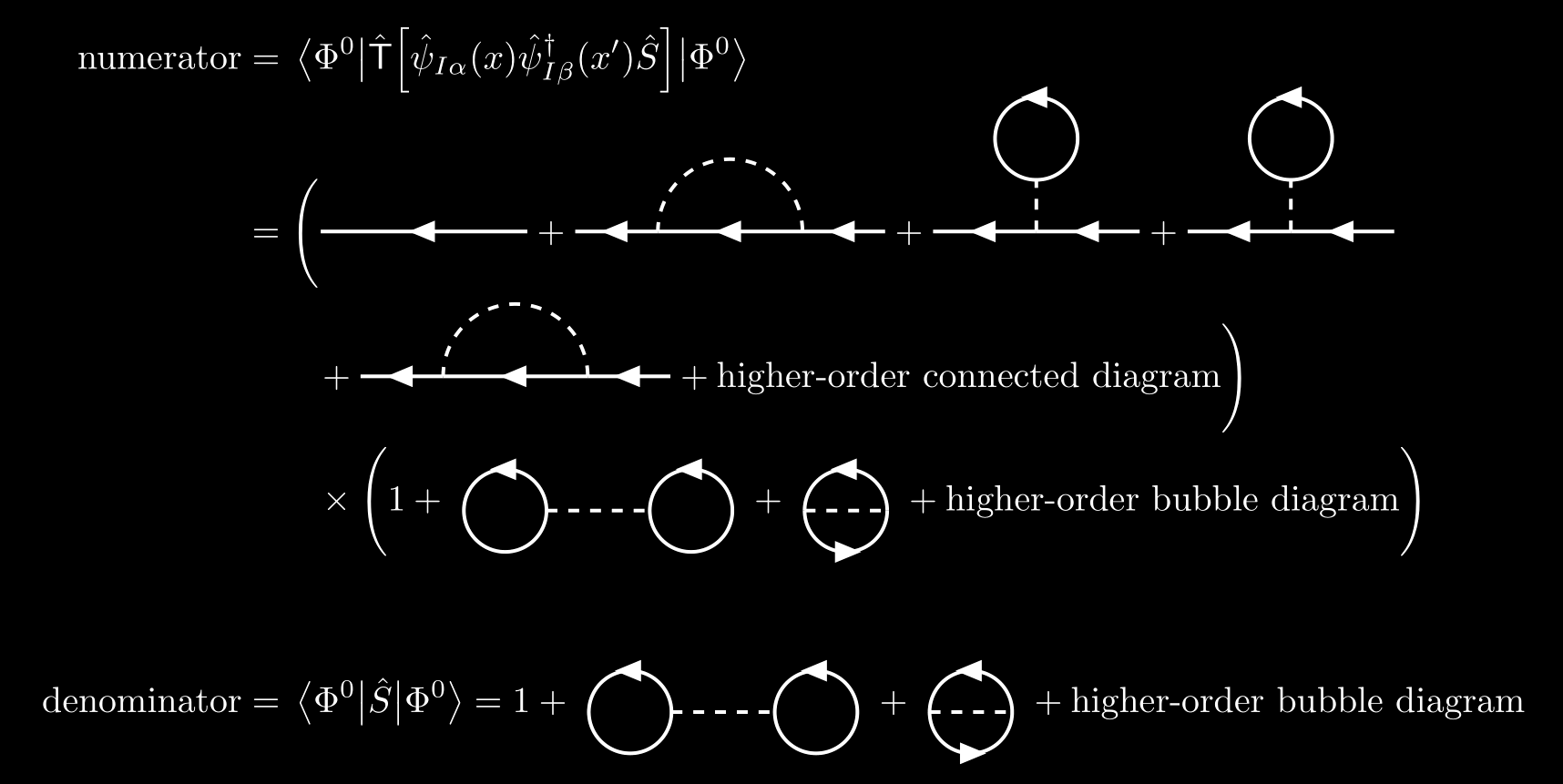
- The terms $a$ and $b$ are disconnected diagrams, containing subunits that are not connected to the rest of the diagram by any lines. These disconnected diagrams do not contribute to the exact Green’s function. This can be simply derived with observation
TikZ code
1
2
3
4
5
6
7
8
9
10
11
12
13
14
15
16
17
18
19
20
21
22
23
24
25
26
27
28
29
30
31
32
33
34
35
36
37
38
39
40
41
42
43
44
45
46
47
48
49
50
51
52
53
54
55
56
57
58
59
60
61
62
63
64
65
66
67
68
69
70
71
72
73
74
75
76
77
78
79
80
81
82
83
84
85
86
87
88
89
90
91
92
93
94
95
96
97
98
99
100
101
102
103
\documentclass{article}
\usepackage[left=5em,right=5em]{geometry}
\usepackage{tikz}
\usepackage{amsmath}
\usepackage{physics}
\usepackage{tikz-feynhand}
\usepackage{tikz-feynman}
\usepackage{subfig}
\setlength{\feynhandlinesize}{1pt}

\begin{document}

\begin{align*}
    \text{numerator}& = \ev{\hat{\mathsf{T}}\qty[\hat{\psi}_{I\alpha}(x)\hat{\psi}_{I\beta}^\dagger(x')\hat{S}]}{\Phi^0}\\[-0.2cm]
    &=\Bigg(
    \begin{tikzpicture}
        \begin{feynhand}
            \vertex (a) at (0,0); \vertex (b) at (2,0);
            \propag[fer] (b) -- (a);
        \end{feynhand}
    \end{tikzpicture}
    +
    \begin{tikzpicture}
        \begin{feynhand}
            \vertex (a) at (0,0); \vertex (b) at (0.8,0); \vertex (c) at (2.2,0);\vertex (d) at (3,0);
            \graph{(d)--[fer] (c) --[fer] (b) --[fer](a)};
            \propag[sca] (c) arc(0:180:0.7);
        \end{feynhand}
    \end{tikzpicture}
    +
    \begin{tikzpicture}
        \begin{feynhand}
            \vertex (a) at (0,0); \vertex (b) at (1,0); \vertex (c) at (2,0); \vertex (d) at (1,0.5);
            \graph{(c)--[fer] (b) --[fer] (a)};
            \propag[sca] (b) -- (d);
            \propag[fer] (d) arc (-90:270:0.4);
        \end{feynhand}
    \end{tikzpicture}
    +
    \begin{tikzpicture}
        \begin{feynhand}
            \vertex (a) at (0,0); \vertex (b) at (1,0); \vertex (c) at (2,0); \vertex (d) at (1,0.5);
            \graph{(c)--[fer] (b) --[fer] (a)};
            \propag[sca] (b) -- (d);
            \propag[fer] (d) arc (-90:270:0.4);
        \end{feynhand}
    \end{tikzpicture}
    \\
    &\qquad
    +
    \begin{tikzpicture}
        \begin{feynhand}
            \vertex (a) at (0,0); \vertex (b) at (0.8,0); \vertex (c) at (2.2,0);\vertex (d) at (3,0);
            \graph{(d)--[fer] (c) --[fer] (b) --[fer](a)};
            \propag[sca] (c) arc(0:180:0.7);
        \end{feynhand}
    \end{tikzpicture}
    + \text{higher-order connected diagram}
    \Bigg)\\
    &\qquad
    \times
    \Bigg(1+\
    \begin{tikzpicture}[baseline=(a.base)]
        \begin{feynhand}
            \vertex (a) at (0,0); \vertex (b) at (1,0);
            \propag[fer] (a) circle [radius=0.4,xshift=-0.4cm,rotate=-90];
            \propag[fer] (b) circle [radius=0.4,xshift=0.4cm,rotate=-90];
            \propag[sca] (a) -- (b);
        \end{feynhand}
    \end{tikzpicture}
    \ +\
    \begin{tikzpicture}[baseline=(a.base)]
        \begin{feynhand}
            \vertex (a) at (0,0); \vertex (b) at (0.8,0);
            \propag[fer] (b) arc (0:180:0.4);
            \propag[fer] (a) arc (180:360:0.4);
            \propag[sca] (a) -- (b);
        \end{feynhand}
    \end{tikzpicture}\ +
    \text{higher-order bubble diagram}
    \Bigg)\\[.8cm]
    \text{denominator}&= \ev{\hat{S}}{\Phi^0}= 1+\
    \begin{tikzpicture}[baseline=(a.base)]
        \begin{feynhand}
            \vertex (a) at (0,0); \vertex (b) at (1,0);
            \propag[fer] (a) circle [radius=0.4,xshift=-0.4cm,rotate=-90];
            \propag[fer] (b) circle [radius=0.4,xshift=0.4cm,rotate=-90];
            \propag[sca] (a) -- (b);
        \end{feynhand}
    \end{tikzpicture}
    \ +\
    \begin{tikzpicture}[baseline=(a.base)]
        \begin{feynhand}
            \vertex (a) at (0,0); \vertex (b) at (0.8,0);
            \propag[fer] (b) arc (0:180:0.4);
            \propag[fer] (a) arc (180:360:0.4);
            \propag[sca] (a) -- (b);
        \end{feynhand}
    \end{tikzpicture}\ +
    \text{higher-order bubble diagram}
\end{align*}

\end{document}
So the contribution of the denominator in $\eqref{green-function}$ exactly cancels the contribution of the disconnected diagrams in the numerator. We therefore obtain the fundamental formula
where $C$ denotes connected, we therefore only need to consider the contribution of the connected diagram.
We summary the following rule for the $n$th-order contribution to the single-particle Green’s function $G_{\alpha\beta}(x,x’)$.
- Draw all topologically distinct connected diagrams with $n$ interaction lines $U$ and $2n+1$ directed Green’s functions $G^0$.
- Label each vertex with a four-dimensional space-time point $x_i$ and its spin index.
- Each solid line represents a Green’s function $G_{\alpha\beta}^0(x,y)$ running from $y,\beta$ to $x,\alpha$.
- Each dashed line represents an interaction $\hat{U}(x,y) = \hat{V}(x,y)\delta(t_x-t_y)$ running from $y$ to $x$.
- Integrate all internal variables over space and time.
- Sum all internal spin indices.
- Affix a sign factor $(-1)^F$ to each term, where $F$ is the number of closed fermion loops in the diagram.
- This overall sign comes from loops in Feynman diagrams. Every time a fermion line closes on itself, the term acquire an extra minus sign.
- Assign a factor $(i/\hbar)^n$ to each $n$th-order term.
- In $\eqref{green-function}$, $iG$ is calculated, and we actually multiply by $-i$ to get $G$.
- These $2n+1$ solid lines represent $2n+1$ free Green’s functions $iG^0$, providing $i^{2n+1}$.
- The coefficient of $n$th order of the expansion $\eqref{green-function}$ is $(-i/\hbar)^n/(n!2^n)$, where $1/2^n$ comes from the interparticle potential $\hat{U}$.
- The $n$th-order term has $n! 2^n$ topologically equivalent diagrams.
- A Green’s function with equal time variables must be interpreted as $G_{\alpha\alpha}^0(y-y) = G_{\alpha\alpha}^0(-\eta)$, where $\eta \to 0^+$.
And it must be emphasized that the detailed structure of the Feynman rules depends on the form of the interaction $\hat{V}$, and the present derivation applies only to a system of identical particles interacting through a two-body potential which is independent of particle’s spin.
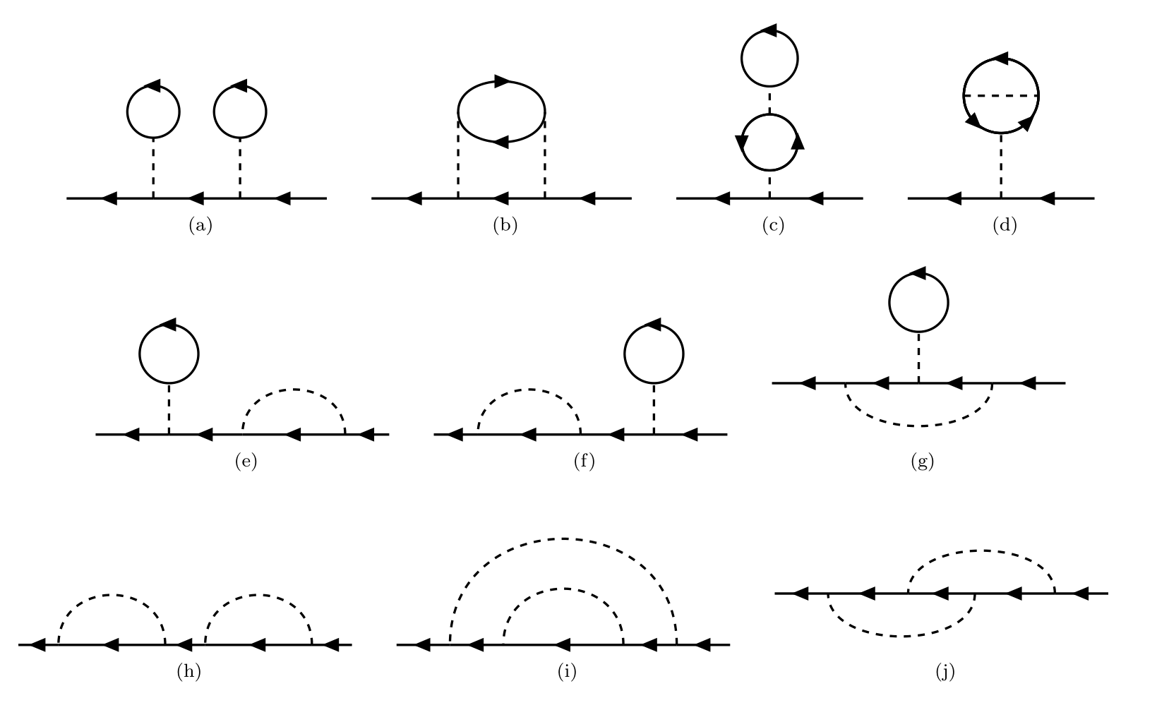
For the 2nd-order contribution to the single-particle Green’s function $G_{\alpha\beta}(x,x’)$, it has $2!\times 2^2=8$ topologically equivalent diagrams.
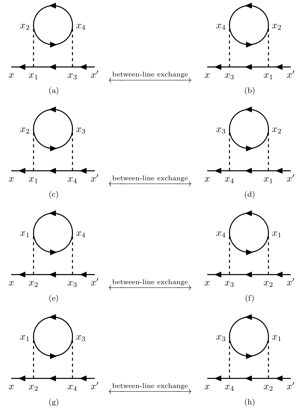
Note that interchange between lines from left to right and within lines from top to bottom.
There are 10 topologically distinct connected diagrams of 2nd-order contribution.
TikZ code
1
2
3
4
5
6
7
8
9
10
11
12
13
14
15
16
17
18
19
20
21
22
23
24
25
26
27
28
29
30
31
32
33
34
35
36
37
38
39
40
41
42
43
44
45
46
47
48
49
50
51
52
53
54
55
56
57
58
59
60
61
62
63
64
65
66
67
68
69
70
71
72
73
74
75
76
77
78
79
80
81
82
83
84
85
86
87
88
89
90
91
92
93
94
95
96
97
98
99
100
101
102
103
104
105
106
107
108
109
110
111
112
113
114
115
116
117
118
119
120
121
122
123
124
125
126
127
128
129
130
131
132
133
134
135
136
137
138
\documentclass{article}
\usepackage[left=1em,right=1em]{geometry}
\usepackage{tikz}
\usepackage{amsmath}
\usepackage{physics}
\usepackage{tikz-feynhand}
\usepackage{tikz-feynman}
\usepackage{subfig}
\usepackage{extarrows}
\setlength{\feynhandlinesize}{1pt}
\setlength{\columnsep}{0.5cm}


\begin{document}

\begin{figure}
    \centering
    \subfloat[]{% a
        \begin{tikzpicture}[scale=1.3]
            \begin{feynhand}
                \vertex (a) at (0,0); \vertex (b) at (1,0); \vertex (c) at (2,0); \vertex (d) at (3,0);
                \vertex (b1) at (1,0.7); \vertex (c1) at (2,0.7);
                \graph{ (d) --[fer] (c) --[fer] (b) --[fer] (a) };
                \propag[fer] (b1) circle [yshift=0.3cm,radius=0.3,rotate=-90];
                \propag[fer] (c1) circle [yshift=0.3cm,radius=0.3,rotate=-90];
                \propag[sca] (b) to (b1); \propag[sca] (c) to (c1);
            \end{feynhand}
        \end{tikzpicture}
    }
    \hspace{.4cm}
    \subfloat[]{% b
        \begin{tikzpicture}[scale=1.3]
            \begin{feynhand}
                \vertex (a) at (0,0); \vertex (b) at (1,0); \vertex (c) at (2,0); \vertex (d) at (3,0);
                \vertex (b1) at (1,1); \vertex (c1) at (2,1);
                \graph{ (d) --[fer] (c) --[fer] (b) --[fer] (a) };
                \propag[fer] (b1) to[in=90,out=90,looseness=1.2] (c1);
                \propag[fer] (c1) to[in=-90,out=-90,looseness=1.2] (b1);
                \propag[sca] (b) to (b1); \propag[sca] (c) to (c1);
            \end{feynhand}
        \end{tikzpicture}
    }
    \hspace{.4cm}
    \subfloat[]{% c
        \begin{tikzpicture}[scale=1.4]
            \begin{feynhand}
                \vertex (a) at (0,0); \vertex (b) at (1,0); \vertex (c) at (2,0);
                \vertex (b1) at (1,0.3); \vertex (b2) at (1,1.2);
                \graph{ (c) --[fer] (b) --[fer] (a) };
                \propag[fer] (b1) circle [yshift=0.3cm,radius=0.3];
                \propag[fer] (b1) circle [yshift=0.3cm,radius=0.3,rotate=180];
                \propag[fer] (b2) circle [yshift=0.3cm,radius=0.3,rotate=-90];
                \propag[sca] (b) to (b1);
                \propag[sca] (1,0.9) -- (b2);
            \end{feynhand}
        \end{tikzpicture}
    }
    \hspace{.4cm}
    \subfloat[]{% d
        \begin{tikzpicture}[scale=1.4]
            \begin{feynhand}
                \vertex (a) at (0,0); \vertex (b) at (1,0); \vertex (c) at (2,0);
                \graph{ (c) --[fer] (b) --[fer] (a) };
                \propag[fer] (1,0.7) circle [yshift=0.4cm,radius=0.4,rotate=-90];
                \propag[fer] (1,0.7) circle [yshift=0.4cm,radius=0.4,rotate=-225];
                \propag[fer] (1,0.7) circle [yshift=0.4cm,radius=0.4,rotate=45];
                \propag[sca] (b) to (1,0.7);
                \propag[sca] (0.6,1.1) to (1.4,1.1);
            \end{feynhand}
        \end{tikzpicture}
    }
    \vspace{.4cm}

    \subfloat[]{% e
        \begin{tikzpicture}[scale=1.1]
            \begin{feynhand}
                \vertex (a) at (0,0); \vertex (b) at (1,0); \vertex (c) at (2,0); \vertex (d) at (3.4,0); \vertex (e) at (4,0);
                \vertex (b1) at (1,0.7);
                \graph{ (e) --[fer] (d) --[fer] (c) --[fer] (b) --[fer] (a) };
                \propag[fer] (b1) circle [yshift=0.4cm,radius=0.4,rotate=-90];
                \propag[sca] (b) to (b1); \propag[sca] (d) to[in=90,out=90,looseness=1.5](c);
            \end{feynhand}
        \end{tikzpicture}
    }\hspace{.4cm}
    \subfloat[]{% f
        \begin{tikzpicture}[scale=1.1]
            \begin{feynhand}
                \vertex (a) at (0,0); \vertex (b) at (0.6,0); \vertex (c) at (2,0); \vertex (d) at (3,0); \vertex (e) at (4,0);
                \vertex (d1) at (3,0.7);
                \graph{ (e) --[fer] (d) --[fer] (c) --[fer] (b) --[fer] (a) };
                \propag[fer] (d1) circle [yshift=0.4cm,radius=0.4,rotate=-90];
                \propag[sca] (d) to (d1); \propag[sca] (c) to[in=90,out=90,looseness=1.5](b);
            \end{feynhand}
        \end{tikzpicture}
    }\hspace{.4cm}
    \subfloat[]{% g
        \begin{tikzpicture}[scale=1.1]
            \begin{feynhand}
                \vertex (a) at (0,0); \vertex (b) at (1,0); \vertex (c) at (2,0); \vertex (d) at (3,0); \vertex (e) at (4,0);
                \vertex (c1) at (2,0.7);
                \graph{ (e) --[fer] (d) --[fer] (c) --[fer] (b) --[fer] (a) };
                \propag[fer] (c1) circle [yshift=0.4cm,radius=0.4,rotate=-90];
                \propag[sca] (c) to (c1); \propag[sca] (d) to[in=-90,out=-90](b);
            \end{feynhand}
        \end{tikzpicture}
    }
    \vspace{.4cm}

    \subfloat[]{% h
        \begin{tikzpicture}
            \begin{feynhand}
                \vertex (a) at (0,0); \vertex (b) at (0.6,0); \vertex (c) at (2.2,0); \vertex (d) at (2.8,0); \vertex (e) at (4.4,0); \vertex (f) at (5,0);
                \graph{ (f) --[fer] (e) --[fer] (d) --[fer] (c) --[fer] (b) --[fer] (a) };
                \propag[sca] (c) to[in=90,out=90,looseness=1.6] (b); \propag[sca] (e) to[in=90,out=90,looseness=1.6](d);
            \end{feynhand}
        \end{tikzpicture}
    }\hspace{.4cm}
    \subfloat[]{% i
        \begin{tikzpicture}
            \begin{feynhand}
                \vertex (a) at (0,0); \vertex (b) at (0.8,0); \vertex (c) at (1.6,0); \vertex (d) at (3.4,0); \vertex (e) at (4.2,0); \vertex (f) at (5,0);
                \graph{ (f) --[fer] (e) --[fer] (d) --[fer] (c) --[fer] (b) --[fer] (a) };
                \propag[sca] (e) to[in=90,out=90,looseness=1.6] (b); \propag[sca] (d) to[in=90,out=90,looseness=1.6](c);
            \end{feynhand}
        \end{tikzpicture}
    }\hspace{.4cm}
    \subfloat[]{% j
        \begin{tikzpicture}
            \begin{feynhand}
                \vertex (a) at (0,0); \vertex (b) at (0.8,0); \vertex (c) at (2,0); \vertex (d) at (3,0); \vertex (e) at (4.2,0); \vertex (f) at (5,0);
                \graph{ (f) --[fer] (e) --[fer] (d) --[fer] (c) --[fer] (b) --[fer] (a) };
                \propag[sca] (e) to[in=90,out=90,looseness=1.0] (c); \propag[sca] (d) to[in=-90,out=-90,looseness=1.0](b);
            \end{feynhand}
        \end{tikzpicture}
    }\hspace{.4cm}
\end{figure}

\end{document}
Examples
Consider the summation of the spin indices in the following two diagrams.
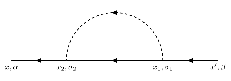
Its contribution is
\[\begin{align*} \widetilde{G}^{(1)}_{\alpha\beta}(x-x') &= \frac{i}{\hbar}\sum_{\sigma_1\sigma_2} \iint\dd[4]{x_1}\dd[4]{x_2} G_{\alpha\sigma_2}^0(x-x_2)G_{\sigma_2\sigma_1}^0(x_2-x_1)G_{\sigma_1\beta}^0(x-x')U(x_2-x_1)\\[.2cm] &=\frac{i}{\hbar}\sum_{\sigma_1\sigma_2} \iint\dd[4]{x_1}\dd[4]{x_2} \delta_{\alpha\sigma_2}G^0(x-x_2)\delta_{\sigma_2\sigma_1}G^0(x_2-x_1)\delta_{\sigma_1\beta}G^0(x-x')U(x_2-x_1)\\[.2cm] &=\frac{i}{\hbar}\sum_{\sigma_1}\iint\dd[4]{x_1}\dd[4]{x_2}G^0(x-x_2)\delta_{\alpha\sigma_1}G^0(x_2-x_1)\delta_{\sigma_1\beta}G^0(x-x')U(x_2-x_1)\\[.2cm] &=\frac{i}{\hbar}\delta_{\alpha\beta}\iint\dd[4]{x_1}\dd[4]{x_2}G^0(x-x_2)G^0(x_2-x_1)G^0(x-x')U(x_2-x_1). \end{align*}\]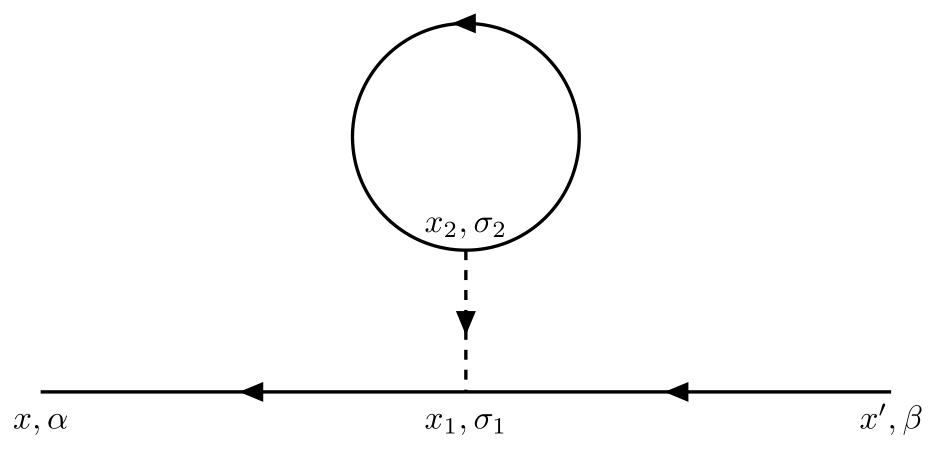
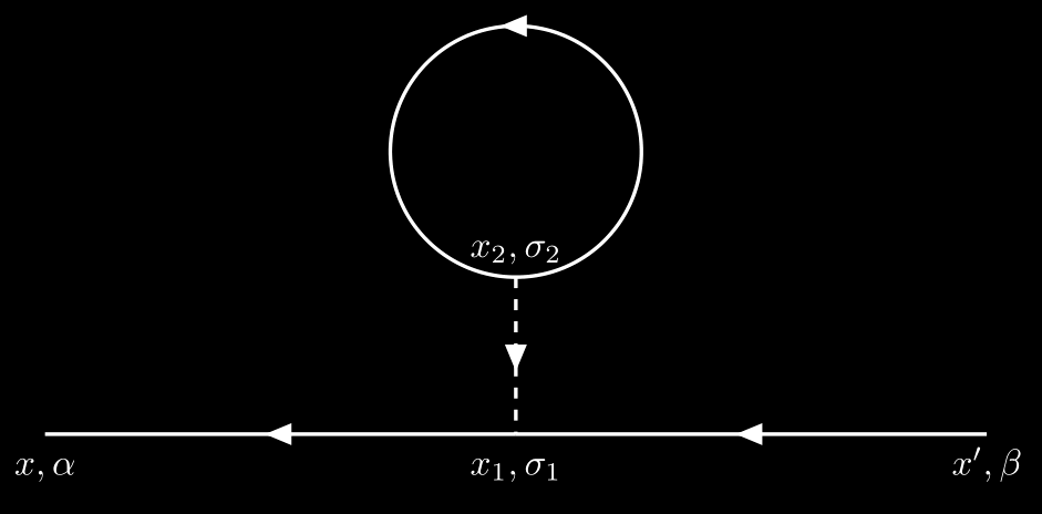
Its contribution is
\[\begin{align*} \widetilde{G}^{(2)}_{\alpha\beta}(x-x') &= -\frac{i}{\hbar} \sum_{\sigma_1\sigma_2}\iint \dd[4]{x_1}\dd[4]{x_2} G_{\alpha\sigma_1}^0(x-x_1)G_{\sigma_1\beta}^0(x_1-x')G_{\sigma_2\sigma_2}^0(x_2-x_2)U(x_2-x_1)\\[.2cm] &= -\frac{i}{\hbar}\sum_{\sigma_1\sigma_2}\iint \dd[4]{x_1}\dd[4]{x_2} \delta_{\alpha\sigma_1}G^0(x-x_1)\delta_{\sigma_1\beta}G^0(x_1-x')\delta_{\sigma_2\sigma_2}G^0(x_2-x_2)U(x_2-x_1)\\[.2cm] &=-\frac{i(2s+1)}{\hbar}\sum_{\sigma_1}\iint \dd[4]{x_1}\dd[4]{x_2} \delta_{\alpha\sigma_1}G^0(x-x_1)\delta_{\sigma_1\beta}G^0(x_1-x')G^0(x_2-x_2)U(x_2-x_1)\\[.2cm] &=-i(2s+1)\delta_{\alpha\beta}\iint \dd[4]{x_1}\dd[4]{x_2} G^0(x-x_1)G^0(x_1-x')G^0(-\eta)U(x_2-x_1), \end{align*}\]where
\[\begin{align*} G^0_{\alpha\beta}(x-x') &= \frac{-i\delta_{\alpha\beta}}{V}\sum_{\mathbf{k}}\qty[\theta(t-t')\theta(\abs{\mathbf{k}}-k_F)-\theta(t'-t)\theta(k_F-\abs{\mathbf{k}})] \e^{i\mathbf{k}\cdot(\mathbf{x}-\mathbf{x}')} \e^{-i\epsilon_{\vb{k}}^0 (t-t')/\hbar},\\[.2cm] \Rightarrow\quad G^0(-\eta)&= \frac{i}{V} \sum_{\vb{k}}\theta(k_F-\abs{\vb{k}}) \theta(\eta) \e^{i\epsilon_{\vb{k}}^0\eta/\hbar} = \frac{i}{2s+1}\frac{N}{V} = \frac{i}{2s+1}n. \end{align*}\]Note that the total particle number is $N = (2s+1)\displaystyle{ \sum_{\vb{k}}}\theta(k_F - \abs{\vb{k}})$ where $2s+1$ represents spin degeneracy. E.g., the total particle number of a free electron system is $N = 2\displaystyle{ \sum_{\vb{k}}}\theta(k_F - \abs{\vb{k}})$. Thus,
\[\begin{align*} \widetilde{G}^{(2)}_{\alpha\beta}(x-x') = \frac{n}{\hbar} \delta_{\alpha\beta}\iint\dd[4]{x_1}\dd[4]{x_2} G^0(x-x_1)G^0(x_1-x')U(x_2-x_1). \end{align*}\]2. Feynman diagrams in momentum space
In principle, the Feynman rules enable us to write down the exact Green’s function to arbitrary order. But it is actually complicated to calculate integrals in coordinate space. In contrast, the noninteracting Green’s function $G^0$ has a very simple form in momentum space. So we shall discuss the Feynman rules in momentum space. Note that we restrict the discussion to uniform and isotropic system, where the exact Green’s function takes the form $\delta_{\alpha\beta}G(x-y)$.
Introduce the four dimensional wave vector as $k = \qty{\vb{k},\omega}$, and $\dd{k}=\dd[3]{\vb{k}}\dd{\omega}$, $k\cdot x = \vb{k}\cdot x - \omega t$. The spatial and temporal invariance then allows a full Fourier representation,
\[\begin{align} \mathrm{F.T.}&\begin{cases} \displaystyle{G_{\alpha\beta}(x-y) = \int\frac{\dd[4]{k}}{(2\pi)^4} G_{\alpha\beta}(k)\e^{ik\cdot(x-y)}},\\[.2cm] \displaystyle{U(x-y) = \int\frac{\dd[4]{k}}{(2\pi)^4} U(k)\e^{ik\cdot(x-y)}}. \end{cases}\\[.4cm] \mathrm{I.F.T.}&\begin{cases} \displaystyle{G_{\alpha\beta}(k) = \int\dd[4]{(x-y)} G_{\alpha\beta}(x-y)\e^{-ik\cdot(x-y)}},\\[.2cm] \displaystyle{U(k) = \int\dd[4]{k} U(x-y)\e^{-ik\cdot(x-y)} = V(\vb{k})}. \end{cases} \end{align}\]There are two special cases which need to be discussed in detail.
If $\vb{x}\neq \vb{x}’,t=t’$, let $t’=t+\eta$
\[\begin{equation} G_{\alpha\beta}^0(x - x') = \int \frac{\dd[4]{k}}{(2\pi)^4}G_{\alpha\beta}^0(\vb{k},\omega) \e^{i\vb{k}\cdot(\vb{x}-\vb{x}')}\e^{i\omega\eta}, \quad \text{where $\eta =t'-t$}. \end{equation}\]If $\vb{x}’ = \vb{x},t’=t$, let $\vb{x}’=\vb{x},t’=t+\eta$
\[\begin{equation} G_{\alpha\beta}^0 (x-x') = \int \frac{\dd[4]{k}}{(2\pi)^4} G_{\alpha\beta}^0(\vb{k},\omega)\e^{i\omega\eta}, \quad \text{where $\eta = t'-t$.} \end{equation}\]
Examples
Consider the Fourier transform of the Green’s functions $\widetilde{G}_{\alpha\beta}^{(1)}(x-x’)$ and $\widetilde{G}_{\alpha\beta}^{(2)}(x-x’)$ in the above examples.
\[\begin{align*} \widetilde{G}_{\alpha\beta}^{(1)}(k) &= \frac{i}{\hbar} \sum_{\sigma_1\sigma_2} \int \frac{\dd[4]{k'}}{(2\pi)^4} G_{\alpha\sigma_2}^0(k)G_{\sigma_2\sigma_1}^0(k')G_{\sigma_1\beta}^0(k)V(\vb{k}-\vb{k}')\e^{i\omega'\eta},\\[.2cm] \widetilde{G}_{\alpha\beta}^{(2)}(k) &= \frac{-i}{\hbar}\sum_{\sigma_1\sigma_2} \int \frac{\dd[4]{k'}}{(2\pi)^4} G_{\alpha\sigma_1}^0(k) G_{\sigma_1\beta}^0(k)G_{\sigma_2\sigma_2}^0(k')V(0)\e^{i\omega'\eta}. \end{align*}\]We can now state the Feynman rules for the $n$th-order contribution to $G_{\alpha\beta}(\vb{k},\omega) := G_{\alpha\beta}(k)$:
- Draw all topologically distinct connected diagrams with $n$ interaction lines and $2n+1$ directed Green’s functions.
- Assign a direction to each interaction line; associate a directed four-momentum with each line and conserve four-momentum at each vertex.
Each Green’s function corresponds to a factor
\[\begin{equation} G_{\alpha\beta}^0(\vb{k},\omega) = \delta_{\alpha\beta}G^0(\vb{k},\omega) = \delta_{\alpha\beta} \qty[\frac{\theta(\abs{\vb{k}}-k_F)}{\omega-\omega_{\vb{k}}+i\eta} + \frac{\theta(k_F - \abs{\vb{k}})}{\omega-\omega_{\vb{k}}-i\eta}], \end{equation}\]where $\epsilon_{\vb{k}}^0 = \hbar \omega_{\vb{k}}$.
- Each interaction corresponds to a factor $U(q) = V(\vb{q})$.
- Integrate over the $n$ independent internal four-momenta.
- Sum all internal spin indices.
- Affix a factor $\qty(\dfrac{i}{\hbar})^n\dfrac{(-1)^F}{(2\pi)^{4n}}$ where $F$ is the number of closed fermion loops.
- Any single-particle line that forms a closed loop or that is linked by the same interaction line is interpreted as $\e^{i\omega \eta} G_{\alpha\beta}(\vb{k},\omega)$, where $\eta\to 0^+$ at the end of the calculation.
Examples
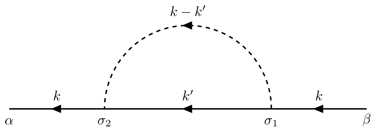
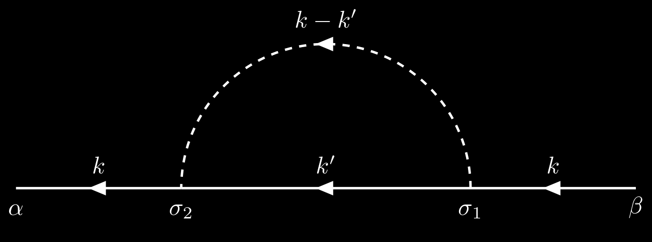
Write down the contribution of the following two diagrams.
Its contribution is
\[\begin{align*} G_{\alpha\beta}^{(1)} &= \frac{i}{\hbar}\sum_{\sigma_1\sigma_2}\int \frac{\dd[4]{k'}}{(2\pi)^4} G_{\alpha\sigma_2}^{0}(k) G_{\sigma_2\sigma_1}^0(k') G_{\sigma_1\beta}^0(k)V(\vb{k}-\vb{k}')\e^{i\omega'\eta}\\[.2cm] &=\frac{i}{\hbar}\sum_{\sigma_1\sigma_2} G_{\alpha\sigma_2}^{0}(k) G_{\sigma_1\beta}^0(k) \int \frac{\dd[4]{k'}}{(2\pi)^4} G_{\sigma_2\sigma_1}^0(k')V(\vb{k}-\vb{k}')\e^{i\omega'\eta}. \end{align*}\]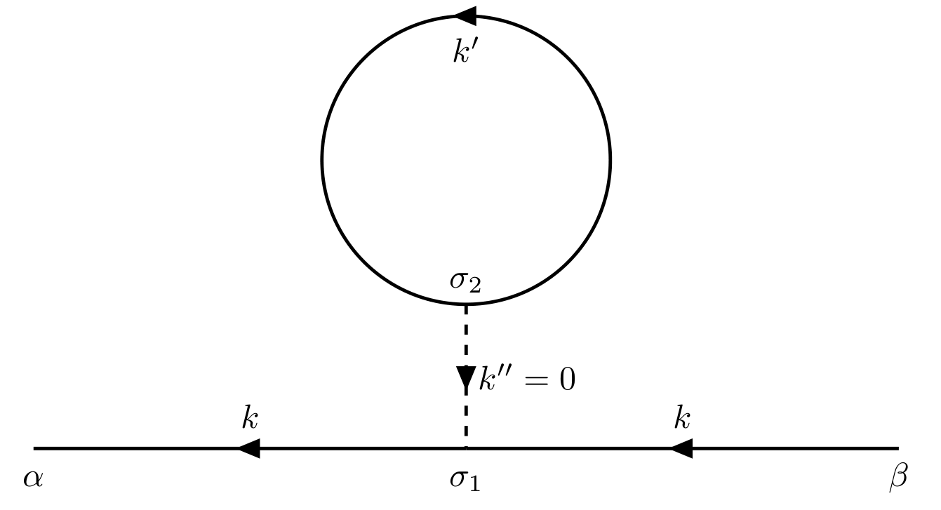
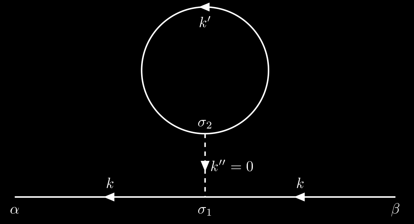
Its contribution is
\[\begin{align*} G_{\alpha\beta}^{(1)} &= -\frac{i}{\hbar}\sum_{\sigma_1\sigma_2}\int \frac{\dd[4]{k'}}{(2\pi)^4} G_{\alpha\sigma_1}^{0}(k)G_{\sigma_1\beta}^0(k) G_{\sigma_2\sigma_2}^0(k') V(0)\e^{i\omega'\eta}\\[.2cm] &=-\frac{i}{\hbar}\sum_{\sigma_1\sigma_2} G_{\alpha\sigma_1}^{0}(k) G_{\sigma_1\beta}^0(k) \int \frac{\dd[4]{k'}}{(2\pi)^4} G_{\sigma_2\sigma_2}^0(k')V(0)\e^{i\omega'\eta}. \end{align*}\]3. Dyson’s equations
3.1. Dyson’s equations in coordinate space
We associate the exact Green’s function $G$ with a double line, and the noninteracting Green’s function $G^0$, with a single line, as illustrated in the following figure.


TikZ code
1
2
3
4
5
6
7
8
9
10
11
12
13
14
15
16
17
18
19
20
21
22
23
24
25
26
27
28
29
\documentclass{article}
\usepackage[left=1em,right=1em]{geometry}
\usepackage{tikz}
\usepackage{amsmath}
\usepackage{physics}
\usepackage{tikz-feynhand}
\usepackage{tikz-feynman}
\usepackage{subfig}
\setlength{\feynhandlinesize}{1pt}
\tikzset{every picture/.style={line width=1pt}}

\begin{document}

\begin{figure}
    \centering
\begin{tikzpicture}[scale=2]
    \begin{feynhand}
        \draw[double distance=1pt, with arrow=0.5] (2,0)node[below]{$x',\beta$}--  (0,0) node[midway,yshift=1em]{$G_{\alpha\beta}(x-x')$} node[below]{\vphantom{$x'$}$x,\alpha$};
    \end{feynhand}
\end{tikzpicture}
\hspace{1cm}
\begin{tikzpicture}[scale=2]
    \begin{feynhand}
        \propag[fer] (2,0)node[below]{$x',\beta$}--  (0,0) node[midway,yshift=1em]{$G^0_{\alpha\beta}(x-x')$} node[below]{\vphantom{$x'$}$x,\alpha$};
    \end{feynhand}
\end{tikzpicture}
\end{figure}

\end{document}
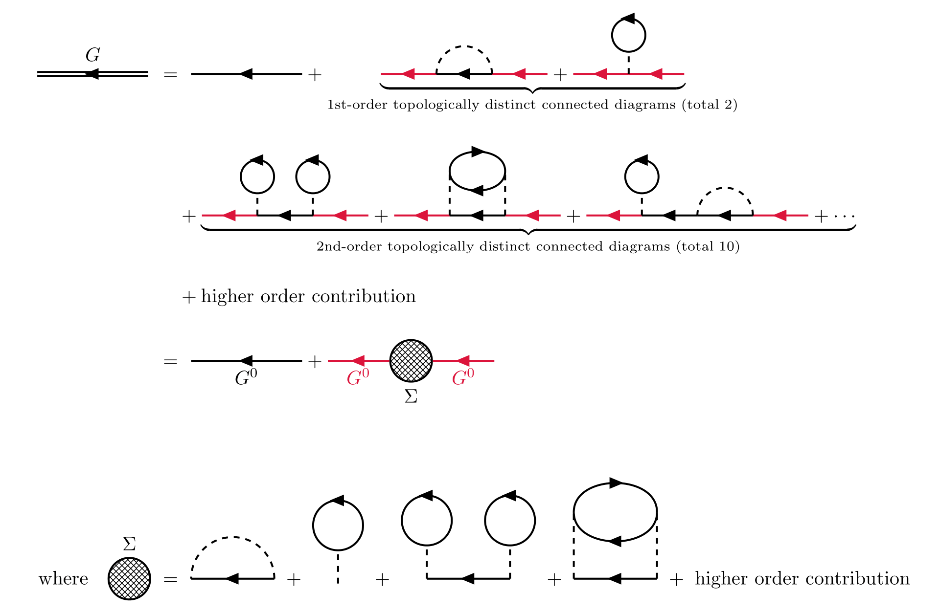
So the expansion of the exact Green’s function $\eqref{exact-green-function}$ can be expressed as
TikZ code
1
2
3
4
5
6
7
8
9
10
11
12
13
14
15
16
17
18
19
20
21
22
23
24
25
26
27
28
29
30
31
32
33
34
35
36
37
38
39
40
41
42
43
44
45
46
47
48
49
50
51
52
53
54
55
56
57
58
59
60
61
62
63
64
65
66
67
68
69
70
71
72
73
74
75
76
77
78
79
80
81
82
83
84
85
86
87
88
89
90
91
92
93
94
95
96
97
98
99
100
101
102
103
104
105
106
107
108
109
110
111
112
113
114
115
116
117
118
119
120
121
122
123
124
125
126
127
128
129
130
131
132
133
134
135
136
137
138
\documentclass[svgnames]{article}
\usepackage[left=1em,right=1em]{geometry}
\usepackage{tikz}
\usepackage{amsmath}
\usepackage{physics}
\usepackage{tikz-feynhand}
\usepackage{tikz-feynman}
\usepackage{subfig}
\usepackage{xcolor}
\usepackage{color}
\setlength{\feynhandlinesize}{1pt}
\tikzset{every picture/.style={line width=1pt}}
\usetikzlibrary{patterns}

\begin{document}

\begin{align*}
    \begin{tikzpicture}
        \begin{feynhand}
            \vertex (a) at (0,0);
            \draw[double distance=1pt, with arrow=0.5] (2,0)--  (0,0) node[midway,yshift=1em]{$G$};
        \end{feynhand}
    \end{tikzpicture}\
 &= \
 \begin{tikzpicture}
    \begin{feynhand}
        \propag[fer] (2,0) to (0,0);
    \end{feynhand}
 \end{tikzpicture}
 + \underbrace{
 \begin{tikzpicture}
    \begin{feynhand}
        \propag[fer,Crimson] (3,0) -- (2,0);
        \propag[fer] (2,0) -- (1,0);
        \propag[fer,Crimson] (1,0) -- (0,0);
        \propag[sca] (2,0) arc(0:180:0.5);
    \end{feynhand}
 \end{tikzpicture}
 +
 \begin{tikzpicture}
    \begin{feynhand}
        \propag[fer,Crimson] (2,0) -- (1,0);
        \propag[fer,Crimson] (1,0) -- (0,0);
        \propag[sca] (1,0) -- (1,0.4);
        \propag[fer] (1,0.4) circle[radius=0.3,yshift=0.3cm,rotate=-90];
    \end{feynhand}
 \end{tikzpicture}}_{\text{1st-order topologically distinct connected diagrams (total 2)}}\\[.4cm]
&\quad {}+\underbrace{
\begin{tikzpicture}
    \begin{feynhand}
        \propag[fer,Crimson] (3,0) -- (2,0);
        \propag[fer] (2,0) -- (1,0);
        \propag[fer,Crimson] (1,0) -- (0,0);
        \propag[sca] (1,0) -- (1,0.4); \propag[fer] (1,0.4) circle[radius=0.3,yshift=0.3cm,rotate=-90];
        \propag[sca] (2,0) -- (2,0.4); \propag[fer] (2,0.4) circle[radius=0.3,yshift=0.3cm,rotate=-90];
    \end{feynhand}
 \end{tikzpicture}
 +
 \begin{tikzpicture}
    \begin{feynhand}
        \propag[fer,Crimson] (3,0) -- (2,0);
        \propag[fer] (2,0) -- (1,0);
        \propag[fer,Crimson] (1,0) -- (0,0);
        \propag[fer] (1,0.8) to[in=90,out=90,looseness=1.2] (2,0.8);
        \propag[fer] (2,0.8) to[in=-90,out=-90,looseness=1.2] (1,0.8);
        \propag[sca] (1,0) to (1,0.8); \propag[sca] (2,0) to (2,0.8);
    \end{feynhand}
\end{tikzpicture}
+
\begin{tikzpicture}
    \begin{feynhand}
        \propag[fer,Crimson] (4,0) -- (3,0);
        \propag[fer] (3,0) -- (2,0);
        \propag[fer] (2,0) -- (1,0);
        \propag[fer,Crimson] (1,0) -- (0,0);
        \propag[sca] (1,0) -- (1,0.4); \propag[fer] (1,0.4) circle[radius=0.3,yshift=0.3cm,rotate=-90];
        \propag[sca] (3,0) arc (0:180:0.5);
    \end{feynhand}
\end{tikzpicture}
+\cdots }_{\text{2nd-order topologically distinct connected diagrams (total 10)}}\\[.4cm]
&\quad{}+{}\text{higher order contribution}\\[.4cm]
&=\
\begin{tikzpicture}[baseline=-3pt]
    \begin{feynhand}
        \propag[fer] (2,0) to (0,0);
        \node at (1,0) [below]{$G^0$};
    \end{feynhand}
 \end{tikzpicture}
 +
 \begin{tikzpicture}[baseline=-3pt]
    \begin{feynhand}
        \vertex (a) at (0,0); \vertex (c) at (3,0);
        \vertex[blob,pattern=crosshatch] (b)  at  (1.5,0) {};
        \node at (b) [yshift=-18pt]{$\Sigma$};
        \graph{(c)--[fer,Crimson,edge label=$G^0$](b)--[fer,Crimson,edge label=$G^0$](a)};
    \end{feynhand}
 \end{tikzpicture}\\[1cm]
 \text{where}\quad
 \begin{tikzpicture}[baseline=-3pt]
    \begin{feynhand}
    \vertex[blob,pattern=crosshatch] (b)  at  (1.5,0) {};
    \node at (b) [yshift=18pt]{$\Sigma$};
\end{feynhand}
 \end{tikzpicture}\
 & =\
 \begin{tikzpicture}[scale=1.5]
    \begin{feynhand}
        \propag[fer] (2,0) -- (1,0);
        \propag[sca] (2,0) arc(0:180:0.5);
    \end{feynhand}
 \end{tikzpicture}\
 +\
 \begin{tikzpicture}[scale=1.5]
    \begin{feynhand}
        \propag[sca] (1,0) -- (1,0.4);
        \propag[fer] (1,0.4) circle[radius=0.3,yshift=0.3cm,rotate=-90];
    \end{feynhand}
 \end{tikzpicture}\
 +\
 \begin{tikzpicture}[scale=1.5]
    \begin{feynhand}
        \propag[fer] (2,0) -- (1,0);
        \propag[sca] (1,0) -- (1,0.4); \propag[fer] (1,0.4) circle[radius=0.3,yshift=0.3cm,rotate=-90];
        \propag[sca] (2,0) -- (2,0.4); \propag[fer] (2,0.4) circle[radius=0.3,yshift=0.3cm,rotate=-90];
    \end{feynhand}
 \end{tikzpicture}\
 +\
 \begin{tikzpicture}[scale=1.5]
    \begin{feynhand}
        \propag[fer] (2,0) -- (1,0);
        \propag[fer] (1,0.8) to[in=90,out=90,looseness=1.2] (2,0.8);
        \propag[fer] (2,0.8) to[in=-90,out=-90,looseness=1.2] (1,0.8);
        \propag[sca] (1,0) to (1,0.8); \propag[sca] (2,0) to (2,0.8);
    \end{feynhand}
\end{tikzpicture}\ +\ \text{higher order contribution}
\end{align*}

\end{document}
So the exact Green’s funtion can always be written in the form
\[\begin{gather} G_{\alpha\beta}^0(x-x') = G_{\alpha\beta}^0(x-x') + \sum_{\gamma\gamma'}\iint\dd[4]{z}\dd[4]{z'} G_{\alpha\gamma}^{0}(x,z)\Sigma_{\gamma,\gamma'}(z,z') G_{\gamma'\beta}^0(z',y). \end{gather}\]where $\Sigma(k)$ is the self-energy. A self-energy insertion is defined as any part of a diagram that is connected to the rest of the diagram by two particle lines (one in and one out). Note that the first term is just the zero-order contribution. The above equations are one of the Dyson’s equations which have be proved via graphical analysis.
We next introduce the concept of a proper self-energy insertion, which is a self-energy insertion that cannot be separated into two pieces by cutting a single particle line $G^0$.
For examples, consider the 10 topologically distinct connected diagrams of 2nd-order contribution, which have been listed in the previous secion. Their self-energy insertions are listed in the following figure.
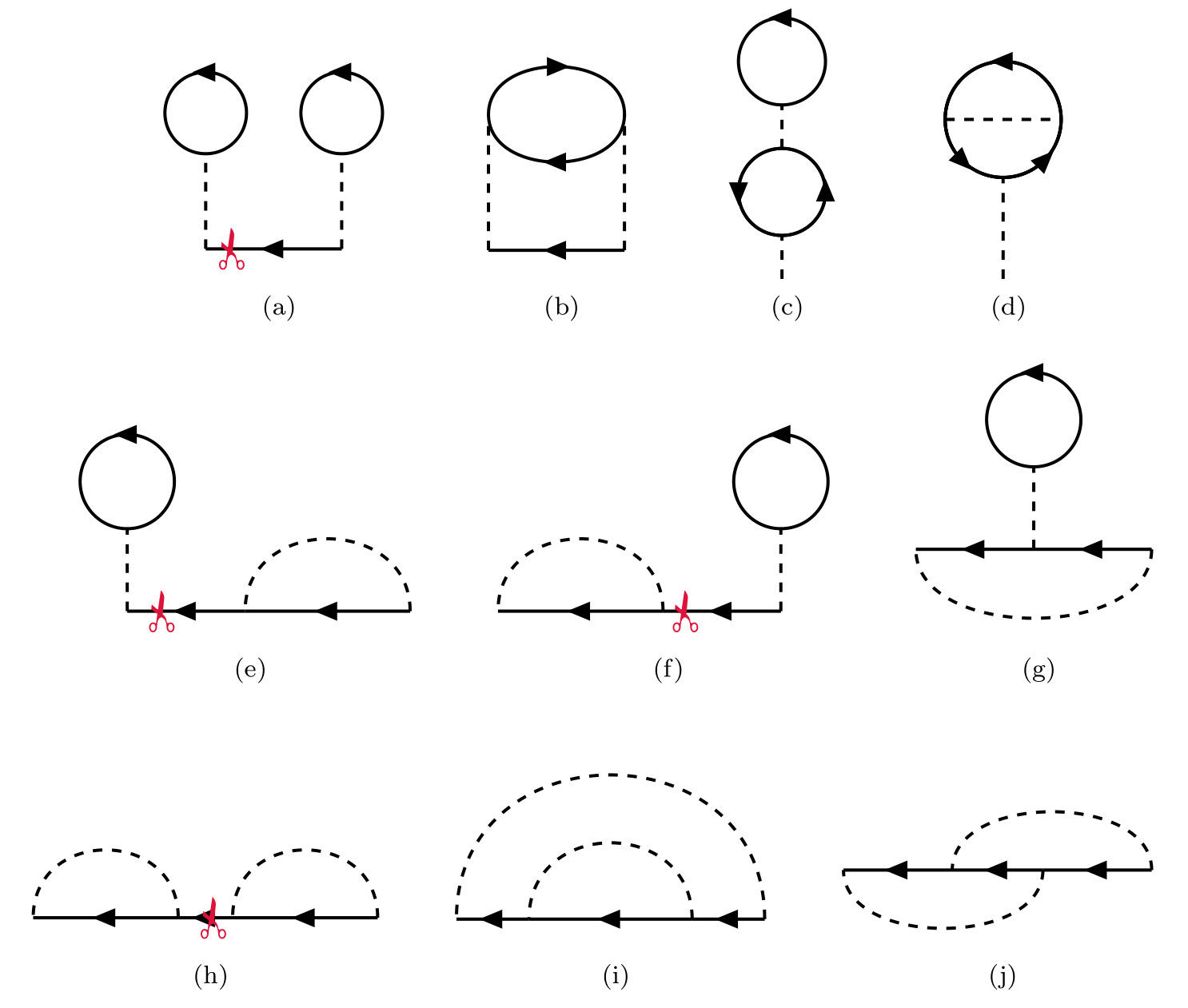
By cutting a single particle line along the red marks in figure (a), (b), (f) and (h), we can get two 1st-order self energy insertions. The others can’t be cut like this.
By definition, the proper self-energy is the sum of all proper self-energy insertions, and will be denoted $\Sigma^\star$. And the self-energy can be expressed via proper self-energy.
TikZ code
1
2
3
4
5
6
7
8
9
10
11
12
13
14
15
16
17
18
19
20
21
22
23
24
25
26
27
28
29
30
31
32
33
34
35
36
37
38
39
40
41
42
43
44
45
46
47
48
49
50
51
52
53
54
55
56
57
58
59
60
61
62
63
64
65
66
67
68
69
70
71
72
73
\documentclass[svgnames]{article}
\usepackage[left=1em,right=1em]{geometry}
\usepackage{xcolor}
\usepackage{color}
\usepackage{tikz}
\usepackage{amsmath}
\usepackage{physics}
\usepackage{tikz-feynhand}
\usepackage{tikz-feynman}
\setlength{\feynhandlinesize}{1pt}
\tikzset{every picture/.style={line width=1pt}}
\usetikzlibrary{patterns}

\begin{document}

\begin{align*}
    \begin{tikzpicture}[baseline=-3pt]
        \begin{feynhand}
        \vertex[blob,pattern=crosshatch, minimum size=1cm] (a)  at  (0,0) {};
        \node at (a) [yshift=22pt]{$\Sigma$};
        \end{feynhand}
     \end{tikzpicture}
     \ &= \
     \begin{tikzpicture}[baseline=-3pt]
        \begin{feynhand}
        \vertex[NWblob,minimum size=1cm] (a)  at  (0,0) {};
        \node at (a) [yshift=22pt]{$\Sigma^\star$};
        \end{feynhand}
     \end{tikzpicture}
     \ + \
     \begin{tikzpicture}[baseline=-3pt]
        \begin{feynhand}
        \vertex[blob,Crimson,pattern=north west lines,pattern color=Crimson,minimum size=1cm] (a)  at  (0,0) {};
        \node at (a) [yshift=22pt,Crimson]{$\Sigma^\star$};
        \vertex[NWblob,minimum size=1cm] (b) at (1.5,0){};
        \node at (b) [yshift=22pt]{$\Sigma^\star$};
        \propag[plain,Crimson] (b) -- (a) node[midway,above,Crimson]{$G^0$};
        \end{feynhand}
     \end{tikzpicture}
     \ + \
     \begin{tikzpicture}[baseline=-3pt]
        \begin{feynhand}
        \vertex[blob,Crimson,pattern=north west lines,pattern color=Crimson,minimum size=1cm] (a)  at  (0,0) {};
        \vertex[NWblob,minimum size=1cm] (b) at (1.5,0){};
        \vertex[NWblob,minimum size=1cm] (c) at (3,0){};
        \node at (a) [yshift=22pt,Crimson]{$\Sigma^\star$};
        \node at (b) [yshift=22pt]{$\Sigma^\star$};
        \node at (c) [yshift=22pt]{$\Sigma^\star$};
        \propag[plain,Crimson] (b) -- (a) node[midway,above,Crimson]{$G^0$};
        \propag[plain] (c) -- (b) node[midway,above]{$G^0$};
        \end{feynhand}
     \end{tikzpicture}
     \ + \cdots\\[.4cm]
        & = \
     \begin{tikzpicture}[baseline=-3pt]
        \begin{feynhand}
        \vertex[NWblob,minimum size=1cm] (a)  at  (0,0) {};
        \node at (a) [yshift=-22pt]{$\Sigma^\star$};
        \end{feynhand}
     \end{tikzpicture}
     \ +\
     \begin{tikzpicture}[baseline=-3pt]
        \begin{feynhand}
            \vertex[blob,Crimson,pattern=north west lines,pattern color=Crimson,minimum size=1cm] (a)  at  (0,0) {};
        \node at (a) [yshift=-22pt,Crimson]{$\Sigma^\star$};
        \vertex[blob,pattern=crosshatch, minimum size=1cm] (b) at (1.5,0){};
        \node at (b) [yshift=-22pt]{$\Sigma^\star$};
        \propag[plain,Crimson] (b) -- (a) node[midway,above,Crimson]{$G^0$};
        \end{feynhand}
     \end{tikzpicture}
\end{align*}

\end{document}
By this diagrammatic analysis, we can get the Dyson’s equation for self-energy $\Sigma$.
\[\begin{equation} \Sigma_{\alpha\beta}(x-x') = \Sigma^\star(x-x') + \sum_{\gamma\gamma'}\iint\dd[4]{z}\dd[4]{z'} \Sigma^\star_{\alpha\gamma}(x-z) G^0_{\gamma\gamma'}(z-z')\Sigma_{\gamma'\beta}(z'-x'). \label{dyson-1} \end{equation}\]Then we can rewritte the exact Green’s function,
TikZ code
1
2
3
4
5
6
7
8
9
10
11
12
13
14
15
16
17
18
19
20
21
22
23
24
25
26
27
28
29
30
31
32
33
34
35
36
37
38
39
40
41
42
43
44
45
46
47
48
49
50
51
52
53
54
55
56
57
58
59
60
61
62
63
64
65
66
67
68
69
70
71
72
73
74
75
76
77
78
79
80
81
82
83
84
85
86
87
88
89
90
91
92
93
94
95
96
97
98
99
100
101
102
103
104
105
106
107
108
109
110
111
112
113
114
115
116
117
118
119
120
121
122
123
124
125
126
127
128
129
130
\documentclass[svgnames]{article}
\usepackage[left=1em,right=1em]{geometry}
\usepackage{tikz}
\usepackage{amsmath}
\usepackage{physics}
\usepackage{tikz-feynhand}
\usepackage{tikz-feynman}
\usepackage{subfig}
\usepackage{xcolor}
\usepackage{color}
\usepackage{bbding}
\setlength{\feynhandlinesize}{1pt}
\tikzset{every picture/.style={line width=1pt}}
\usetikzlibrary{patterns}

\begin{document}

\begin{align*}
    \begin{tikzpicture}[scale=0.8]
        \begin{feynhand}
            \vertex (a) at (0,0);
            \draw[double distance=1pt, with arrow=0.5] (2,0)--  (0,0) node[midway,yshift=1em]{$G$};
        \end{feynhand}
    \end{tikzpicture}
    \ &= \
    \begin{tikzpicture}[scale=0.8]
        \begin{feynhand}
            \propag[fer] (2,0) to (0,0);
        \end{feynhand}
     \end{tikzpicture}
     \ + \
     \begin{tikzpicture}[baseline=-3pt,scale=0.8]
        \begin{feynhand}
            \vertex (a) at (0,0); \vertex (c) at (3,0);
            \vertex[blob,pattern=crosshatch] (b)  at  (1.5,0) {};
            \graph{(c)--[fer](b)--[fer](a)};
        \end{feynhand}
     \end{tikzpicture}\\[.3cm]
     & = \
     \begin{tikzpicture}[scale=0.8]
        \begin{feynhand}
            \propag[fer] (2,0) to (0,0);
        \end{feynhand}
     \end{tikzpicture}
     \ + \
     \begin{tikzpicture}[baseline=-3pt,scale=0.8]
        \begin{feynhand}
            \vertex (a) at (0,0); \vertex (c) at (3,0);
            \vertex[blob,Crimson,pattern=north west lines,pattern color=Crimson] (b)  at  (1.5,0) {};
            \graph{(c)--[fer](b)--[fer,Crimson](a)};
        \end{feynhand}
     \end{tikzpicture}
     \ + \
     \begin{tikzpicture}[baseline=-3pt,scale=0.8]
        \begin{feynhand}
            \vertex (a) at (0,0); \vertex (d) at (4.5,0);
            \vertex[blob,Crimson,pattern=north west lines,pattern color=Crimson] (b)  at  (1.5,0) {};
            \vertex[NWblob,] (c)  at  (3,0) {};
            \graph{(d)--[fer](c)--[fer](b)--[fer,Crimson](a)};
        \end{feynhand}
     \end{tikzpicture}
     \ + \
     \begin{tikzpicture}[baseline=-3pt,scale=0.8]
        \begin{feynhand}
            \vertex (a) at (0,0); \vertex (e) at (6,0);
            \vertex[blob,Crimson,pattern=north west lines,pattern color=Crimson] (b)  at  (1.5,0) {};
            \vertex[NWblob,] (c)  at  (3,0) {};
            \vertex[NWblob,] (d)  at  (4.5,0) {};
            \graph{(e)--[fer](d)--[fer](c)--[fer](b)--[fer,Crimson](a)};
        \end{feynhand}
     \end{tikzpicture}
     \ + \cdots\\[.3cm]
     &= \
    \begin{tikzpicture}[scale=0.8]
        \begin{feynhand}
            \propag[fer] (2,0) to (0,0);
        \end{feynhand}
     \end{tikzpicture}
     \ + \
     \begin{tikzpicture}[baseline=-3pt,scale=0.8]
        \begin{feynhand}
            \vertex (a) at (0,0);
            \vertex[blob,Crimson,pattern=north west lines,pattern color=Crimson] (b)  at  (1.5,0) {};
            \graph{(b)--[fer,Crimson](a)};
        \end{feynhand}
     \end{tikzpicture}
     \ \Bigg\{
        \
        \begin{tikzpicture}[scale=0.8]
           \begin{feynhand}
               \propag[fer] (2,0) to (0,0);
           \end{feynhand}
        \end{tikzpicture}
        \ + \
        \begin{tikzpicture}[baseline=-3pt,scale=0.8]
           \begin{feynhand}
               \vertex (a) at (0,0); \vertex (c) at (3,0);
               \vertex[NWblob] (b)  at  (1.5,0) {};
               \graph{(c)--[fer](b)--[fer](a)};
           \end{feynhand}
        \end{tikzpicture}
        \ + \
        \begin{tikzpicture}[baseline=-3pt,scale=0.8]
           \begin{feynhand}
               \vertex (a) at (0,0); \vertex (d) at (4.5,0);
               \vertex[NWblob] (b)  at  (1.5,0) {};
               \vertex[NWblob,] (c)  at  (3,0) {};
               \graph{(d)--[fer](c)--[fer](b)--[fer](a)};
           \end{feynhand}
        \end{tikzpicture}
        \ + \cdots \Bigg\}\\[.3cm]
    &=\
    \begin{tikzpicture}[scale=0.8,baseline=-3pt]
        \begin{feynhand}
            \propag[fer] (2,0) to[edge label=$G^0$] (0,0);
        \end{feynhand}
        \end{tikzpicture}
    \ +\
    \begin{tikzpicture}[baseline=-3pt,scale=0.8]
        \begin{feynhand}
            \vertex (a) at (0,0);
            \vertex[blob,Crimson,pattern=north west lines,pattern color=Crimson] (b)  at  (1.5,0) {};
            \graph{(b)--[fer,Crimson,edge label=$G^0$](a)};
            \draw[double distance=1pt, with arrow=0.5] (3,0)--  (2,0) node[midway,below]{$G$};
            \node at (1.5,-0.5)[below,Crimson]{$\Sigma^\star$};
        \end{feynhand}
     \end{tikzpicture}
\end{align*}

\end{document}
We therefore obtain another form of Dyson’s equation,
\[\begin{gather} G_{\alpha\beta}(x-x') = G_{\alpha\beta}^0(x-x') + \sum_{\gamma\gamma'} \iint \dd[4]{z}\dd[4]{z'}G_{\alpha\gamma}^0(x-z) \Sigma_{\gamma\gamma'}^\star(z-z') G_{\gamma'\beta}(z'-x'). \label{dyson-2} \end{gather}\]This Dyson’s equation is an integral equation in coordinate space and cannot be solved simply. To address this, we want to swich it to momentum space.
3.2. Dyson’s equation in momentum space
We also introduce the four-dimensional Fouiere transforms for the proper self-energy,
\[\begin{equation} \Sigma^\star_{\alpha\beta}(x-y) =\int \frac{\dd[4]{k}}{(2\pi)^4} \Sigma^\star_{\alpha\beta} (k) \e^{ik\cdot (x-y)}, \end{equation}\]where $\Sigma_{\alpha\beta}^\star (k) = \delta_{\alpha\beta} \Sigma^\star(k)$ if the interatcion is independent of particle’s spin.
The Dyson’s equation $\eqref{dyson-1}$ in momentum space becomes
\[\begin{equation} \Sigma(k) = \Sigma^\star(k) G^0(k) \Sigma(k) \quad \Rightarrow \quad \Sigma(k) = \frac{\Sigma^\star(k)}{1- G^0(k)\Sigma^\star(k)}. \end{equation}\]And the Dyson’s equation $\eqref{dyson-2}$ in momentum space becomes
\[\begin{equation} G(k) = G^0(k) + G^0 \Sigma^\star (k) G(k). \end{equation}\]This Dyson’s equation is an algebraic equation and can be solved explicitly as
\[\begin{equation} G(k) = \frac{1}{\qty[G^0(k)]^{-1} - \Sigma^\star(k)}, \end{equation}\]where
\[G^0(k) = \frac{1}{\omega - \epsilon_{\vb{k}}^0/\hbar + i \eta\, \mathrm{sgn}(\abs{\vb{k}}-k_F)}.\]The $i\eta$ in above equation is now irrelevant because $\Sigma^\star$ is a complex number in general. Then we find
\[\begin{equation} G(k) = \frac{1}{\omega - \hbar^{-1}\epsilon_{\vb{k}}^0 - \Sigma^\star(k)}. \end{equation}\]As shown in previous post, the singularities of the exact Green’s function $G(\vb{k},\omega)$, considered as a function of $\omega$, determine both the excitation energies $\epsilon_{\vb{k}}$ of the system and their damping $\gamma_{\vb{k}}$. Furthermore, the Lehmann represenation ensures that for real $\omega$, we have
- $\mathrm{Im}\, \Sigma^\star (\vb{k},\omega) \geq 0,$ if $\omega <\mu/\hbar$,
- $\mathrm{Im}\, \Sigma^\star (\vb{k},\omega) \leq 0,$ if $\omega >\mu/\hbar$,
so that the chemical potential can be determined as the point where $\mathrm{Im}\, \Sigma^\star(\vb{k},\omega)$ changes sign.
3.3. Polarization insertion
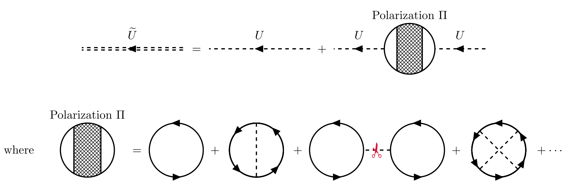
A similar analysis can be carried out for the interaction between two particles. For effective intraction $\widetilde{U}$, it always consists of the lowest-order interaction plus a series of connected diagrams with lowest-order interactions coming in and out.
TikZ code
1
2
3
4
5
6
7
8
9
10
11
12
13
14
15
16
17
18
19
20
21
22
23
24
25
26
27
28
29
30
31
32
33
34
35
36
37
38
39
40
41
42
43
44
45
46
47
48
49
50
51
52
53
54
55
56
57
58
59
60
61
62
63
64
65
66
67
68
69
70
71
72
73
74
75
76
77
78
79
80
81
82
83
84
85
86
87
88
89
90
91
92
93
94
95
96
97
98
99
100
101
102
103
104
105
106
107
108
109
\documentclass[svgnames]{article}
\usepackage[left=1em,right=1em]{geometry}
\usepackage{tikz}
\usepackage{amsmath}
\usepackage{physics}
\usepackage{tikz-feynhand}
\usepackage{tikz-feynman}
\usepackage{subfig}
\usepackage{xcolor}
\usepackage{color}
\usepackage{bbding}
\setlength{\feynhandlinesize}{1pt}
\tikzset{every picture/.style={line width=1pt}}
\usetikzlibrary{patterns}

\newcommand{\polorization}[2]{
  \begin{scope}[shift={(#1)},scale={#2}]
    \begin{scope}
      \clip (-0.5,-1) rectangle (0.5,1);
      \fill[pattern=crosshatch] (0,0) circle (1);
    \end{scope}
    \draw (-0.5,-1.732/2) -- (-0.5,1.732/2);
    \draw (0.5,-1.732/2) -- (0.5,1.732/2);
    \draw (0,0) circle (1);
  \end{scope}
}

\begin{document}

\begin{gather*}
    \begin{tikzpicture}[scale=1.5]
        \begin{feynhand}
            \vertex (a) at (0,0);
            \draw[dashed,double distance=1pt, with arrow=0.5] (2,0)--  (0,0);
            \node at (1,0)[yshift=13pt]{$\widetilde{U}$};
        \end{feynhand}
    \end{tikzpicture}
    \ = \
    \begin{tikzpicture}[baseline=-3pt,scale=1.5]
        \begin{feynhand}
            \propag[chasca] (2,0) to (0,0);
            \node at (1,0)[yshift=13pt]{\vphantom{$\widetilde{U}$}$U$};
        \end{feynhand}
        \end{tikzpicture}
    \ +\
    \begin{tikzpicture}[baseline=-3pt,scale=1.5]
        \begin{feynhand}
            \propag[chasca] (1,0) to (0,0);
            \node at (0.5,0)[yshift=13pt]{\vphantom{$\widetilde{U}$}$U$};
            \polorization{1.5,0}{0.5}
            \propag[chasca] (3,0) to (2,0);
            \node at (2.5,0)[yshift=13pt]{\vphantom{$\widetilde{U}$}$U$};
            \node at (1.5,0.5)[above]{Polarization $\Pi$};
        \end{feynhand}
     \end{tikzpicture}\\[.8cm]
     \text{where}\quad
     \begin{tikzpicture}[baseline=-3pt]
        \begin{feynhand}
            % \draw[pattern=crosshatch] (1,-0.5) rectangle (2,0.5);
            \polorization{(1.5,0)}{0.8}
            \node at (1.5,0.8)[above]{Polarization $\Pi$};
        \end{feynhand}
     \end{tikzpicture}
      = \
     \begin{tikzpicture}[baseline=-3pt,scale=0.8]
        \begin{feynhand}
            \propag[fer] (2,0) arc (0:180:1);
            \propag[fer] (0,0) arc (180:360:1);
        \end{feynhand}
     \end{tikzpicture}
     \ + \
     \begin{tikzpicture}[baseline=-3pt,scale=0.8]
        \begin{feynhand}
            \propag[fer] (1,0) circle [radius=1,rotate=-45];
            \propag[fer] (1,0) circle [radius=1,rotate=-135];
            \propag[fer] (1,0) circle [radius=1,rotate=45];
            \propag[fer] (1,0) circle [radius=1,rotate=135];
            \propag[sca] (1,1) -- (1,-1);
        \end{feynhand}
     \end{tikzpicture}
     \ + \
     \begin{tikzpicture}[baseline=-3pt,scale=0.8]
        \begin{feynhand}
            \propag[fer] (2,0) arc (0:180:1);
            \propag[fer] (0,0) arc (180:360:1);
            \propag[sca] (3,0) -- (2,0);
            \node[rotate=90,Crimson] at (2.5,0){\large\ScissorRightBrokenTop};
            \propag[fer] (5,0) arc (0:180:1);
            \propag[fer] (3,0) arc(180:360:1);
        \end{feynhand}
     \end{tikzpicture}
     \ + \
     \begin{tikzpicture}[baseline=-3pt,scale=0.8]
        \begin{feynhand}
            \propag[fer] (0,0) circle [radius=1,rotate=30];
            \propag[fer] (0,0) circle [radius=1,rotate=90];
            \propag[fer] (0,0) circle [radius=1,rotate=150];
            \propag[fer] (0,0) circle [radius=1,rotate=210];
            \propag[fer] (0,0) circle [radius=1,rotate=270];
            \propag[fer] (0,0) circle [radius=1,rotate=330];
            \draw[dashed] (-45:1) -- (135:1);
            \draw[dashed] (45:1) -- (-135:1);
        \end{feynhand}
     \end{tikzpicture}
     \ + \cdots
\end{gather*}


\end{document}
We can evidently write an integral equation for the exact interaction in coordinate space. But it has a simpler form in momentum space as before
\[\begin{equation} \widetilde{U}(k) = U(k) + U(k) \Pi(k)U(k), \end{equation}\]which defines the polarization insertion $\Pi(q)$. It is also convenient to introduce the concept of a proper polarization $\Pi^\star$, which is a polarization part that cannot be separated into two polarization parts by cutting a single interaction line $U$. For example, the third diagrams of $\Pi$ in the above figure can be separated into two polarization parts by cutting a single interaction line, so it is not a proper polarization.
TikZ code
1
2
3
4
5
6
7
8
9
10
11
12
13
14
15
16
17
18
19
20
21
22
23
24
25
26
27
28
29
30
31
32
33
34
35
36
37
38
39
40
41
42
43
44
45
46
47
48
49
50
51
52
53
54
55
56
57
58
59
60
61
62
63
64
65
66
67
68
69
70
71
72
73
74
75
76
77
78
79
80
81
82
83
84
85
86
87
88
89
90
91
\documentclass[svgnames]{article}
\usepackage[left=1em,right=1em]{geometry}
\usepackage{tikz}
\usepackage{amsmath}
\usepackage{physics}
\usepackage{tikz-feynhand}
\usepackage{tikz-feynman}
\usepackage{subfig}
\usepackage{xcolor}
\usepackage{color}
\usepackage{bbding}
\setlength{\feynhandlinesize}{1pt}
\tikzset{every picture/.style={line width=1pt,scale=0.9}, baseline={(current bounding box.center)}}
\usetikzlibrary{patterns}

\newcommand{\polorization}[2]{
  \begin{scope}[shift={(#1)},scale={#2}]
    \begin{scope}
      \clip (-0.5,-1) rectangle (0.5,1);
      \fill[pattern=crosshatch] (0,0) circle (1);
    \end{scope}
    \draw (-0.5,-1.732/2) -- (-0.5,1.732/2);
    \draw (0.5,-1.732/2) -- (0.5,1.732/2);
    \draw (0,0) circle (1);
  \end{scope}
}
\newcommand{\properpolorization}[2]{
  \begin{scope}[shift={(#1)},scale={#2}]
    \begin{scope}
      \clip (-0.5,-1) rectangle (0.5,1);
      \fill[pattern=north west lines] (0,0) circle (1);
    \end{scope}
    \draw (-0.5,-1.732/2) -- (-0.5,1.732/2);
    \draw (0.5,-1.732/2) -- (0.5,1.732/2);
    \draw (0,0) circle (1);
  \end{scope}
}
\newcommand{\cproperpolorization}[2]{
  \begin{scope}[shift={(#1)},scale={#2},color=Crimson]
    \begin{scope}
      \clip (-0.5,-1) rectangle (0.5,1);
      \fill[pattern=north west lines,pattern color=Crimson] (0,0) circle (1);
    \end{scope}
    \draw (-0.5,-1.732/2) -- (-0.5,1.732/2);
    \draw (0.5,-1.732/2) -- (0.5,1.732/2);
    \draw (0,0) circle (1);
  \end{scope}
}

\begin{document}

\begin{align*}
    \begin{tikzpicture}[baseline=0pt]
            \polorization{0,0}{1}
            \node at (0,1)[above]{$\Pi$};
    \end{tikzpicture}
   \ &= \
    \begin{tikzpicture}
        \properpolorization{0,0}{1}
    \end{tikzpicture}
    \ +\
    \begin{tikzpicture}
        \cproperpolorization{0,0}{1}
        \draw[dashed,Crimson] (1,0) -- (2,0);
        \properpolorization{3,0}{1}
    \end{tikzpicture}
    \ + \
    \begin{tikzpicture}
        \cproperpolorization{0,0}{1}
        \draw[dashed,Crimson] (1,0) -- (2,0);
        \properpolorization{3,0}{1}
        \draw[dashed] (4,0) -- (5,0);
        \properpolorization{6,0}{1}
    \end{tikzpicture}
    \ + \cdots \\[.4cm]
    & = \
    \begin{tikzpicture}[baseline=-3pt]
        \properpolorization{0,0}{1}
        \node at (0,-1)[below]{$\Pi^\star$};
    \end{tikzpicture}
    \ + \
    \begin{tikzpicture}[baseline=-3pt]
        \cproperpolorization{0,0}{1}
        \node at (0,-1)[below,Crimson]{$\Pi^\star$};
        \draw[dashed,Crimson] (1,0)--(2,0) node [midway,below]{$U$};
        \polorization{3,0}{1}
        \node at (3,-1)[below]{$\Pi$};
    \end{tikzpicture}
\end{align*}

\end{document}
So we can get the Dyson’s equation for polorization $\Pi$.
\[\begin{equation} \Pi(k) = \Pi^\star(k) + \Pi^\star(k) U(k) \Pi(k) \quad \Rightarrow \quad \Pi(k) = \frac{\Pi^\star(k)}{1- U(k)\Pi^\star(k)}. \end{equation}\]This result can be used to define a generalized dielectric function $\kappa(k)$,
\[\begin{equation} \widetilde{U}(k) = \frac{U(k)}{\kappa(k)} \quad \Rightarrow \quad \kappa(k) = 1- U(k)\Pi^\star(k), \end{equation}\]which characterizes the modification of the lowest-order interaction by the poloarization of the medium.
4. References
- Fetter, A. L., Walecka, J. D. Quantum Theory of Many-Particle Systems. Courier Corporation (2002).
- Mahan, G. D., Many-Particle Physics. Springer Science+Business Media, LLC. (2000).
- Altland, A., Simons, B. D., Condensed Matter Field Theory. Cambridge University Press. (2010)
- 金彪. 量子多体理论. 2024年春
